Viewed products


Confianza Online


domoticalia.es/es/ Reviews with ekomi.es

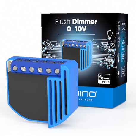
Qubino Flush Dimmer 0-10V

ZMNHVD1

New

Intelligent lighting (smarthome lighting) and LED regulation (dimmer). Universal regulation module (dimmer) with a standard 0-10V output and a multifunction input, which could be a pushbutton, switch, potentiometer or a 0 to 10 volt signal (0-10V)

More details

Out of stock

73,10 €

Technical characteristics

Technology Z-Wave Plus
Characteristic Dimmer

More info

Qubino Flush Dimmer 0-10V: the only dimmer or dimmer 0-10V Z-Wave universal

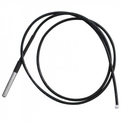
The Qubino Flush Dimmer 0-10V is a universal dimmer with a standard 0-10V output and a multifunction input, which can be a button or switch, a potentiometer or a 0-10V signal. It also measures the power consumption and supports the connection of a digital temperature sensor.

What is it for?

The Qubino Flush Dimmer 0-10V is ideal for regulating LED lights either by remote control and home automation for lighting systems with low voltage ballast.

The Qubino Flush Dimmer 0-10V is a Z-Wave Plus product currently UNIQUE and exclusive of its kind . It has been researched and developed based on DIY users and enthusiasts who have been desperately looking for a Z-Wave solution with a 0-10V input / output. The Qubino Flush Dimmer 0-10V has resulted in the perfect dimmer for LED lighting.

The smallest Z-Wave dimmer

The module Z-Wave Qubino Flush Dimmer 0-10V is a micromodule that occupies less space than any other module with which it is compared to any other competitor and will fit easily into any conventional mechanism box.

Qubino Flush Dimmer 0-10

Energy control

The dimmer Z-Wave Qubino Flush Dimmer 0-10V , makes measurement of electrical consumption of the connected electrical device and of itself, when it is in "standby" only consumes 0.5 W.

Very versatile

The Qubino Flush Dimmer 0-10V , can operate through an extensive range of temperatures from cold -10ÚC to suffocating 40ÚC (14Ú 104ÚF). It supports the connection of a digital temperature sensor, which is also useful for creating complex scenarios. Each module also acts as a repeater in order to improve the range and stability of the Z-Wave network.

The simplest installation

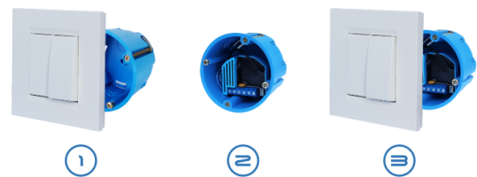
The extremely small size and a specially designed housing mean that the connection of the module inside a recessed mounting box is simple. The installation process, tested and approved by professional electricians , consists of only three simple steps:

1 - Remove the switches from the box and disconnect the cables.
2 - Connect the cables to the Qubino module and insert them into the box.
3 - Fix the switches to the box.
The most proven and reliable Z-Wave modules

Qubino's Z-Wave modules are install-and-forget products. The Qubino products that we offer, are manufactured to last, so they only use electronic components that meet the most demanding levels of quality. Our modules are also the most tested Z-Wave micromodules on the market. The Slovenian Institute of Quality and Measurement (SIQ), an independent European entity, checks the quality of the actual parameters of our products, including temperature increases, manufacturing, insulation resistance, electrical consumption and overloads according to European standards of the highest quality according to the specification of standard EN 60669-2-1.

Additional parameters for professionals.

The Qubino Flush Dimmer 0-10V micromodule   It has 25 additional parameters for its use by experts. Some of the most useful are:

  • Allows input adjustment based on the type of device (switch, potentiometer, 0-10V sensor, etc.)
  • Automatic on / off output after set time

The Qubino Flush Dimmer 0-10V micromodule can be controlled both through a Z-Wave network and through a wall switch. This module has been designed to be mounted inside a mechanism box and hidden behind a conventional wall switch.

Technical specifications and electrical diagrams:
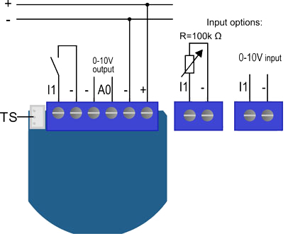
Qubino Flush Dimmer 0-10

Feeding: 12 24 VDC

Max. Control voltage of "sinking"

-20 / +20 VDC
Maximum supply control voltage 0 11 VDC
Max. sinking current 2 mA
Max. sourcing current 7 mA
Accuracy of the power measurement: <3% FS
Digital temperature sensor range: -50 ° ~ + 125 ° C, resolution 0.1 ° C
Cable length of the digital temperature sensor: 1000 mm
Operating Temperature: -10 ° ~ + 40 ° C
Distance up to 30 m indoors (depending on materials)
Dimensions (WxHxD) 41.8 x 36.8 x 15.4 mm
(packaging) (115 x 96 x 22)
Weight (including packaging) 28 g (34 g)
Electric consumption on standby 0.5 W
For installation in mechanism boxes Ø e 60 mm or 2 M

Meets CE and ROHS Certifications

Download

Extended Z-Wave info

Name: Qubino Flush Dimmer 0-10V
Manufacturer:QUBINO
Identifier:ZMNHVD1
Z-Wave Certification Number:ZC10-17025424
Hardware Plattform:ZM5202
FLiRS:NO
Role Type:Always On Slave
Short Description:The Qubino Flush Dimmer 0-10V is ideal for remotely dimming LED lights with low voltage ballast.
Description:The Qubino Flush Dimmer 0-10V is a universal dimmer with a standard 0-10V output and a multi-function input, which may be a push button or switch, a potentiometer or a 0-10V signal. It also measures power consumption and supports the connection of a digital temperature sensor.

Manual download HERE.

Group
Max Nodes
Description
1
1
Z-Wave Plus Lifeline
2
16
Basic On/Off
3
16
Start Level Change/Stop Level Change
4
16
Multilevel Set
5
16
Multilevel Sensor Report (triggered at change of analogue sensor)
6
16
Multilevel Sensor Report (triggered at change of temperature sensor)
Number
Size (Bytes)
Default Value
Name
Description
1
1
0
Input 1 switch type
By this parameter the user can set input based on device type (switch, potentiometer, 0-10V sensor,..). NOTE: After parameter change to value 3, 4 or 5 first exclude module (without setting parameters to default value) then wait at least 30s and then re include the module!
10
2
255
Activate / deactivate functions ALL ON / ALL OFF
Flush Dimmer 0-10V module responds to commands ALL ON / ALL OFF that may be sent by the main controller or by other controller belonging to the system.
11
2
0
Automatic turning off output after set time
Turns off the output after set time.
110
2
32536
Temperature sensor offset settings
Set value is added or subtracted to actual measured value by sensor.
12
2
0
Automatic turning on output after set time
Turns on the output after set time.
120
1
5
Digital temperature sensor reporting
Digital temperature sensor reporting If digital temperature sensor is connected, module reports measured temperature on temperature change defined by this parameter. Available configuration parameters (data type is 1 Byte DEC): • default value 5 = 0,5°C change • 0 - Reporting disabled • 1 - 127 = 0,1°C - 12,7°C, step is 0,1°C
140
2
5
Input I1 Sensor reporting
Input I1 Sensor reporting If analogue sensor is connected, module reports measured value on change defined by this parameter.
141
1
5
Input I1 0-10V reporting threshold
Parameter is associated with Association group No. 2. Below this value, the Association No. 2 will report Basic Set 0xFF and above this value will report Basic Set 0xFF. Basic Set is reported only, when the input value changes for more than 10% (1V).
143
2
0
Minimum sensor range value
Value that must correspond to minimum sensor range value. Valid only if parameter 1 is set to values 3, 4 or 5). Available configuration parameters (data type is 2 Byte DEC): • default value 0 = 0.0°C / 0Lux / 0.0%rh • 0 - 10000 – value from 0 to 1000 (resolution 0,1) • 10001 – 20000 – value from -0,1 to -1000 (resolution 0,1) NOTE: Minimum value must not be higher than maximum value!
144
2
1000
Maximum sensor range value
Value that must correspond to maximum sensor range value. Valid only if parameter 1 is set to values 3, 4 or 5). NOTE: Maximum value must not be lower than minimum value!
21
1
0
Enable/Disable Double click function
If Double click function is enabled, a fast double click on the push button will set dimming power at maximum dimming value. Valid only if input is set as mono-stable (push button).
250
1
0
Unsecure / Secure Inclusion
A Flush dimmer supports secure and unsecure inclusion. Even if the controller does not support security command classes, a dimmer could be included as unsecure and keep all the functionality.
30
1
0
Saving the state of the device after a power failure
Based on the parameter settings the stores/does not store the last value of the output after power failure.
52
1
0
Auto or manual selection
This parameter is influencing on the software only when the value of parameter number 1 is set to value 3, 4 or 5. In manual mode regulation (how the input influence on output) is disabled.
53
1
0
PID value inside deadband
NOTE: When ZERO PID inside deadband is forced to zero. LASTVALUE means that PID remains on same level as was before entering into deadband.
54
1
1
PID deadband
NOTE: This parameter defines the zone where PID is not active. If the temperature difference between actual and setpoint is bigger than PID deadband, then the PID will start to regulate the system, otherwise the PID is zero or fixed.
55
1
5
Integral sampling time
Parameter defines the time between samples. On each sample the controller capture difference between SP-act.
56
2
100
P parameter
The error is multiplied by a negative (for reverse action) proportional constant P, and added to the current output. P represents the band over which a controller's output is proportional to the error of the system. E.g. for a heater, a controller with a proportional band of 10 deg C and a setpoint of 100 deg C would have an output of 100% up to 90 deg C, 50% at 95 Deg C and 10% at 99 deg C. If the temperature overshoots the setpoint value, the heating power would be cut back further. Proportional only control can provide a stable process temperature but there will always be an error between the required setpoint and the actual process temperature.
57
2
1
I parameter
The error is integrated (averaged) over a period of time, and then multiplied by a constant I, and added to the current control output. I represents the steady state error of the system and will remove setpoint / measured value errors. For many applications Proportional + Integral control will be satisfactory with good stability and at the desired setpoint.
58
2
1
D parameter
The rate of change of the error is calculated with respect to time, multiplied by another constant D, and added to the output. The derivative term is used to determine a controller's response to a change or disturbance of the process temperature (e.g. opening an oven door). The larger the derivative term, the more rapidly the controller will respond to changes in the process value.
60
1
1
Minimum dimming value
NOTE: The minimum level may not be higher than the maximum level! 1% min. dimming value is defined by Z-Wave multilevel device class. When the switch type is selected as Bi-stable, it is not possible to dim the value between min and max. If Switch_multilevel_set is set to the value “0”, the output is turned OFF. If Switch_multilevel_set is set to the value “1”, the output is set to the minimum diming value.
61
1
99
Maximum dimming value
NOTE: The maximum level may not be lower than the minimum level! 99% max. dimming value is defined by Z-Wave multilevel device class. When the switch type is selected as Bi-stable, it is not possible to dim the value between min and max.
65
2
100
Dimming time (soft on/off)
Set value means time of moving the Flush Dimmer 0-10V between min. and max. dimming values by short press of push button I1 or controlled through UI (BasicSet).
66
2
3
Dimming time when key pressed
Time of moving the Flush Dimmer 0-10V between min. and max dimming values by continues hold of push button I1 or associated device.
67
1
0
Ignore start level
This parameter is used with association group 3. A receiving device SHOULD respect the start level if the Ignore Start Level bit is 0. A receiving device MUST ignore the start level if the Ignore Start Level bit is 1.
68
1
0
Dimming duration
This parameter is used with association group 3. The Duration field MUST specify the time that the transition should take from the current value to the new target value. A supporting device SHOULD respect the specified Duration value.
Basic
COMMAND_CLASS_BASIC
Switch Multilevel V3
COMMAND_CLASS_SWITCH_MULTILEVEL_V3
Association Group Information V2
COMMAND_CLASS_ASSOCIATION_GRP_INFO_V2
Association V2
COMMAND_CLASS_ASSOCIATION_V2
Basic
COMMAND_CLASS_BASIC
Configuration
COMMAND_CLASS_CONFIGURATION
Device Reset Locally
COMMAND_CLASS_DEVICE_RESET_LOCALLY
Manufacturer Specific V2
COMMAND_CLASS_MANUFACTURER_SPECIFIC_V2
Multi-Channel Association V3
COMMAND_CLASS_MULTI_CHANNEL_ASSOCIATION_V3
Multi-Channel V4
COMMAND_CLASS_MULTI_CHANNEL_V4
Powerlevel
COMMAND_CLASS_POWERLEVEL
Security S0
COMMAND_CLASS_SECURITY
Sensor Multilevel V7
COMMAND_CLASS_SENSOR_MULTILEVEL_V7
Switch All
COMMAND_CLASS_SWITCH_ALL
Switch Binary
COMMAND_CLASS_SWITCH_BINARY
Switch Multilevel V3
COMMAND_CLASS_SWITCH_MULTILEVEL_V3
Version V2
COMMAND_CLASS_VERSION_V2
Z-Wave Plus Info V2
COMMAND_CLASS_ZWAVEPLUS_INFO_V2
Exclusion
• Connect module to power supply

• bring module within maximum 1 meter (3 feet) of the main controller,

• enable add/remove mode on main controller,

• press push button I1 five times within 3s (5 times change switch state within 3 seconds) in the first 60 seconds after the module is connected to the power supply or

• press service button S (only applicable for 24 V SELV supply voltage) for more than 6 second.

By this function all parameters of the module are set to default values and own ID is deleted.

If push button I1 is pressed three times within 3s (or service button S is pressed more than 2 and less than 6 seconds) module is excluded, but configuration parameters are not set to default values.


NOTE 1: If the module is included with parameter 1 value 3, 4 or 5 and module reset is done, wait at least 30s before next inclusion.


NOTE 2: Please use this procedure only when the network primary controller is missing or otherwise inoperable.

Factory Reset
• Press push button I1 five times within 3s (5 times change switch state within 3 seconds) in the first 60 seconds after the module is connected to the power supply or

• press service button S (only applicable for 24 V SELV supply voltage) for more than 6 second.


Please use this procedure only when the network primary controller is missing or otherwise inoperable.
Inclusion
• Connect module to power supply (with

temperature sensor connected - if purchased),

• enable add/remove mode on main controller

• auto-inclusion (works for about 5 seconds after connected to power supply) or

• press service button S for more than 2 second or

• press push button I1 three times within 3s (3 times change switch state within 3 seconds).


NOTE1: For auto-inclusion procedure, first set main controller into inclusion mode and then connect module to power supply.

NOTE2: When connecting temperature sensor to module that has already been included, you have to exclude module first. Switch off power supply, connect the sensor and re-include the module.

Color
If the product is only available in one color, pick the color from the list.
Sensors
Sensor types supported by the product.
Switch Type
Describes the type of operator for a switch.
Switch Load Capacity Current
The amount of switch load energy the product is rated for in Amps


Reviews

Write a review

Qubino Flush Dimmer 0-10V

Qubino Flush Dimmer 0-10V

Intelligent lighting (smarthome lighting) and LED regulation (dimmer). Universal regulation module (dimmer) with a standard 0-10V output and a multifunction input, which could be a pushbutton, switch, potentiometer or a 0 to 10 volt signal (0-10V)

Accessories

Customers who bought this product also bought: