No products
Prices are tax included
Product successfully added to your shopping cart
There are 0 items in your cart. There is 1 item in your cart.
Viewed products
-

Heatit ZM Thermostat...
The Heatit ZM thermostat is a Z-Wave...
-

FIBARO - Mounting...
Mounting frame for mounting devices...


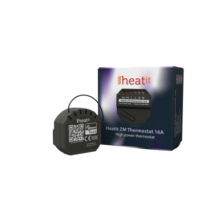
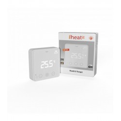
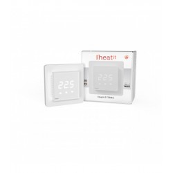
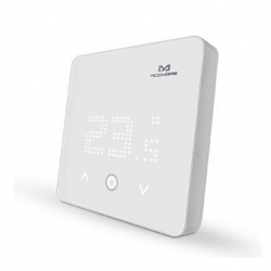
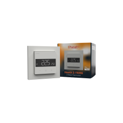
Heatit ZM Thermostat 16A - Z-Wave Thermostat 16A
4512673
New
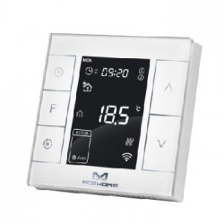
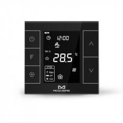
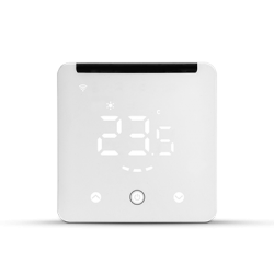
The Heatit ZM thermostat is a Z-Wave electronic thermostat for electric underfloor heating, or for controlling 220V solenoid valves for water underfloor heating, designed for wall mounting, in micromodule format.
In Stock
- Remove this product from my favorite's list.
- Add this product to my list of favorites.
Technical characteristics
| Home Automation Technology | Z-Wave 700 Series |
More info
Heatit ZM Thermostat is an electronic thermostat for electric underfloor heating designed for built-in installations. The thermostat allows you to control your electric heating through your Z-Wave network.
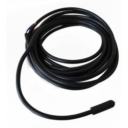
The module is equipped with a 16A relay. The thermostat requires you to connect an external wired sensor, which is included.
The Heatit ZM thermostat has active power measurement and provides you with real-time information about your energy consumption.
Z-Wave
Thermostat for inwall installations
16A/3600W resistive loads
NTC 10k© sensor (included)
Setpoint to be set in gateway
SmartStart
Firmware update (OTA)
Active power metering
Supports encryption mode: S0, S2 Authenticated Class, S2 Unauthenticated Class
IOT/SMART HOME SPECIFIC DATA
Z-Wave Z-Wave Frequency - 868.4 MHz (EU)
Z-Wave Chip Z-Wave 700 Chip
Alternative IoT communication
procols
There are no communication protocols
protocols
Minimum radio frequency range 40m
Over The Air (OTA) Update Yes
Z-Wave S0 encryption mode
S2 Authenticated Class
S2 Unauthenticated class
Z-Wave Plus Certifications
ELECTRICAL TECHNICAL DATA
Voltage 230V 50Hz
Maximum load (resistive load) 3600W
Maximum current 16A
Own consumption 1W
Ambient temperature range in
use
5 to 40°C
Min ambient humidity and max.
(HR%)
10 to 85%.
Connection type Screw clamps
Diameter of the connection terminals from 0.2 to 2.5 mm².
Maximum tightening torque
connections
2N-m
Protection degree (IP) IP20
Declarations CE Declaration
THERMOSTAT DATA
Regulation temperature 5 to 40°C
Extended Z-Wave info
Manual download HERE.
Remove mode is indicated on the device by a blinking green LED. It indicated this for 90 seconds until a timeout occurs, or until the module has been removed from the network. To start the configuration process, press the configuration button 3 times in rapid succession. The LED will light up green for 3 seconds if removing is successful.
Paragraph 11.2 Overheating.
1. On the product.
2. On the Quick Guide manual.
3. On the F-Pack (gift box).
There are two ways to add the device to a Z-Wave network.
Method 1: Standard (Manual)
Add mode is indicated on the device by a blinking green LED. It indicated this for 90 seconds until a timeout occurs, or until the module has been added to the network. To start the configuration process, press the configuration button 3 times in rapid succession. The LED will light up green for 3 seconds if adding is successful.
The device is now ready for use with default settings.
Method 2: SmartStart (Automatic)
SmartStart enabled products may be added to a Z-Wave network by scanning the Z-Wave QR-Code on the product if your primary controller supports SmartStart inclusion. No further action is required and the SmartStart product will be added automatically after being powered on within range of the primary controller.


