No products
Prices are tax included
Product successfully added to your shopping cart
There are 0 items in your cart. There is 1 item in your cart.
Viewed products
-

FIBARO Wall Plug GEN 5...
The Fibaro wall plug is an extremely...
-

AJAX MotionProtect...
Wireless motion detector with...


FIBARO Wall Plug GEN 5 Plug Z-Wave (on / off) with consumption meter
FGWPF-102-5
New
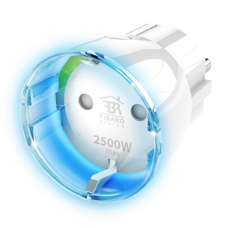
The Fibaro wall plug is an extremely compact Z-Wave Plus smart plug module, which can control the lighting or other equipment connected to your outlet. It is the smallest controlled plug by Z-Wave on the market.
In Stock
- Remove this product from my favorite's list.
- Add this product to my list of favorites.
Technical characteristics
| Home Automation Technology | Z-Wave Plus |
| Characteristic | Consumption Measurement |
More info
The Fibaro controlled plug is an intelligent and extremely compact module, which allows you to control lighting and other devices through Z-Wave commands. It is designed to work with any type of electrical load of up to 2500W of maximum power.
This module also has the function of measuring the energy consumption. Therefore, the instantaneous consumption values and the total consumption are sent to the Z-Wave Control Unit. A visual indicator also allows to know at a glance the consumption: a luminous ring type LED green indicates a low consumption of energy, while a luminous ring type red LED, indicates a very high consumption.
This module also offers a unique feature: the ability to test the coverage of the Z-Wave network. Just press a few seconds of the module key, the violet light LED informs you that the system is in test mode, allowing you to see the current coverage by the color shown.
A Z-Wave Control Unit (controller) is necessary to integrate this module into the network. Each Z-Wave module acts as a wireless repeater with other modules to ensure total coverage in your home.
CHARACTERISTICS:
- It allows to control a lamp or an electrical device.
- Integrates directly into an outlet (plug type schuko)
- The most compact on the market, which allows the use of adjacent plugs
- ON / OFF control of lamps or appliances
- Measurement of the power consumption of the connected load
- Warning in case of overload (> 2500W)
- Alert if the temperature is> 55 ° C
- Load control locally through the built-in button
- Indicates real-time consumption thanks to its light ring
- Unique feature: Z-Wave network coverage test
- Protection of manipulated by children and night light function
- Upgradeable via radio ZWave with Fibaro Home Center 2
- Ease of use and installation
SPECIFICATIONS:
- Module type: Z-Wave / Z-Wave Plus receiver
- Power supply: 110-230 V AC ± 10% 50 / 60Hz
- Maximum power: 2.5 kW
- Consumption: 0.8 W
- Frequency: 868.42 MHz
- Transmission distance: in open field 50 meters, 30 meters in construction
- Dimensions: 43 x 65 mm (diameter x height)
- Operating temperature: 0º - 40 ° C
- Temperature limit: 105 ° C
- Standards: EN 55015 and EN 60669-2-1
 |
 |
Extended Z-Wave info
Manual download HERE.
2) The LED ring will glow green signalling being added (removing is not necessary otherwise).
3) Set the main Z-Wave controller into remove mode (see the controller’s manual).
4) Quickly, triple click the B-button located on the casing.
5) Wait for the removing process to end.
6) Successful removing will be confirmed by the Z-Wave controller.
2) The LED ring will glow red signalling not being added (remove the device otherwise).
3) Set the main Z-Wave controller into adding mode (see the controller’s manual).
4) Quickly, triple click the B-button located on the casing.
5) Wait for the adding process to end.
6) Successful adding will be confirmed by the Z-Wave controller.
FIBARO Wall Plug is powered with mains voltage so it is always awake.
Z-Wave network. Use reset procedure only if the primary controller is missing or
inoperable. Certain device removal can be achieved by the procedure of removing
described in “Adding/ removing the device”on page 6.
1) Make sure the device is powered.
2) Press and hold the B-button.
3) Wait for the LED ring to glow yellow (4th menu position).
4) Release the B-button.
5) Click the B-button once to confirm selection.
6) After few seconds the device will restart with factory settings, which is signalled with the red ring colour.


