No products
Prices are tax included
Product successfully added to your shopping cart
There are 0 items in your cart. There is 1 item in your cart.
Viewed products
-

FIBARO - Walli Dimmer
The FIBARO Walli Dimmer regulator is...
-

-

Eutonomy - euFIX S214...
The euFIX S214 NP adapter is used to...


FIBARO - Walli Dimmer
FGWDEU-111
New
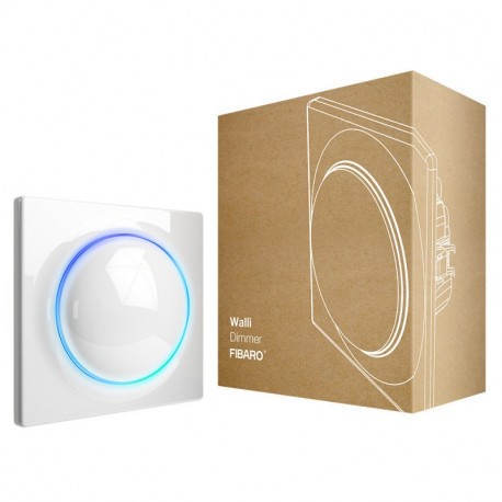
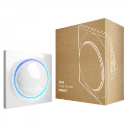
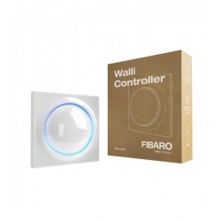
The FIBARO Walli Dimmer regulator is a smart regulator with integrated light switch. Compatible with Z-Wave +.
Out of stock
- Remove this product from my favorite's list.
- Add this product to my list of favorites.
Technical characteristics
| Home Automation Technology | Z-Wave Plus |
| Characteristic | Dimmer |
More info
Intelligent Dimmer Switch Z-Wave + Fibaro Walli Dimmer
FIBARO Walli Dimmer is a smart dimmer with integrated light switch. It works with lighting sources available in the market, such as: LEDs, compact lamps, traditional bulbs and halogen lamps. The device is equipped with automatic calibration and measurement functions for active power and energy.
Unique design and exceptional technology
The complete series of FIBARO smart switches and connectors based on Z-Wave technology will provide your home with versatile intelligence. The look of the series is inspired by a pearl - its timeless sophistication and beautiful form that completes any interior.
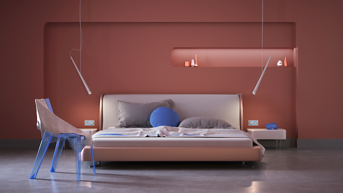
LED ring to match your home
Choose your favorite color
Select the color of the LED ring to adapt it to your personal preferences.
Double backlight button
Use two colors of backlighting wherever you want - a different color on the bottom and another on the top to see the exact status of the device.
An overview of energy consumption
Control the amount of energy consumed by the equipment in your home.
Reliable components and eye-catching details
At FIBARO, unique quality and design always go hand in hand. The Walli line has been designed to improve the comfort and safety of your family for many years.
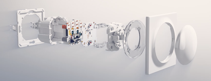
Pulsations to taste
Configure the Walli switch button to take full advantage of its amazing capabilities.
A single click to turn on the light, a double click to turn it off, a triple click to turn on the "Fun" scene, a pulsation maintained for 60% light intensity.
Compatible with products from other manufacturers
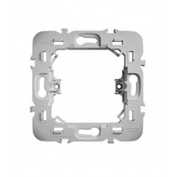
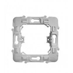
FIBARO Walli is compatible (with adapters) with front plates from other manufacturers: GIRA - System 55, Legrand - Céliane, Schneider - Odace. If connected to existing sockets and switches, equip them with an integrated smart part and enjoy the features of a smart home without having to replace the front panel.

Manage the whole house with voice
Walli's smart switches and sockets are fully compatible with the famous voice assistants of Google Assistant and Amazon Alexa. Easy and comfortable voice management of the entire house.

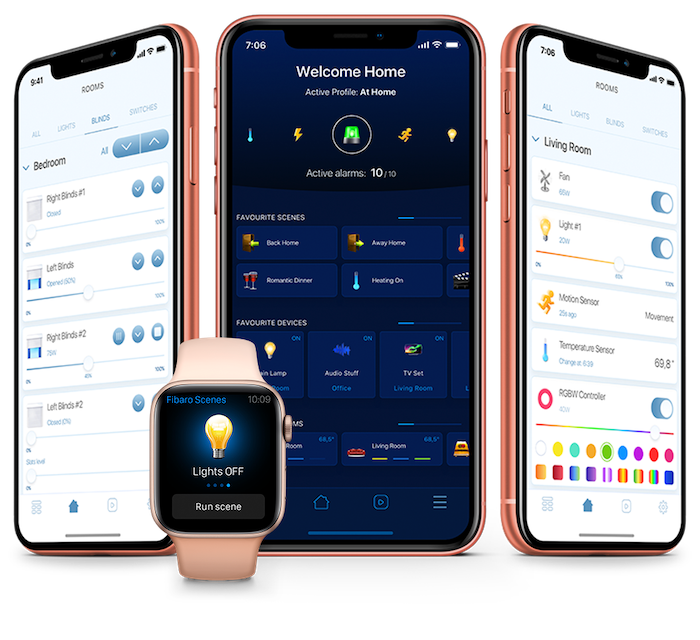
Be with your home wherever you are
The FIBARO Home Center mobile application allows you to manage switches and smart outlets with your smartphone, tablet or smartwatch. Keep everything under control like a boss.
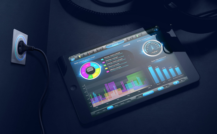
Consumption of controlled energy
Take a look at your home, analyze the energy consumption of your appliances and optimize your expenses as you have always wanted.
Take a step forward into the future
The Walli series from FIBARO includes classic and non-intelligent switches and sockets to keep the aesthetics of your home constant. Choose them as you wish and enjoy a unique design and features.

FUNCTIONS:
Remote management of lighting.
Control of light through voice commands.
Adaptation of the luminous ring to the preferences of the user.
Notifications of electrical equipment failures.
Control of energy consumption.
TECHNICAL SPECIFICATIONS
Power: 110-230V 50 / 60Hz
Rated load current:
Resistive: incandescent and halogen 0.22-1.52A (50-350W)
Capacitive resistance: fluorescent tube lamp (compact / electronic ballast), electronic transformer, LED 0.22-1.3A (30-300VA)
Resistive-inductive: ferromagnetic transformers 0.22-1.3A (30-300VA)
With FIBARO Bypass 2: fluorescent tube or LED lamp (power factor> 0.5) 0.022-0.22A (5-50W)
Radio frequency: 868.0-868.6 MHz
Scope: up to 40 m indoors (depending on the terrain and the structure of the building)
Maximum transmission power: + 6dBm
Operating temperature: 0-35 ° C
Ambient humidity: 10-95% RH without condensation
For installation in boxes: Ø = 60mm, depth e 40mm
Dimensions (H x W x D): 86 x 86 x 51mm
All the documentation and instructions of the Fibaro products are available on the website manuals.fibaro.com
Extended Z-Wave info
Manual download HERE.
1. Quickly, three times click, then press and hold one of the buttons to enter menu.
2. Release the button when the device glows yellow.
3. Quickly click the button to confirm.
4. After a few seconds the device will be restarted, which is signalled with the red LED colour.
Please include a request to use the reset procedure only when the primary controller is missing or inoperable.
1. Set the main controller into remove mode (see the controller’s manual).
2. Quickly, three times click one of the buttons.
3. LED will start blinking yellow, wait for the removing process to end.
4. Successful removing will be confirmed by the Z-Wave controller’s message and red LED colour.
5. The device will start calibrating the load.
1. Set the main controller in (Security/non-Security Mode) add mode (see the controller’s manual).
2. Quickly, three times click one of the buttons.
3. If you are adding in Security S2 Authenticated, scan the DSK QR code or input the underlined part of the DSK (label on the bottom of the box).
4. LED will start blinking yellow, wait for the adding process to end.
5. Adding result will be confirmed by the Z-Wave controller’s message and the LED frame:
- Green - successful (non-secure, S0, S2 non-authenticated),
- Magenta - successful (Security S2 Authenticated),
- Red – not successful.
To add the device to the Z-Wave network using Smart Start:
1. Set the main controller in Security S2 Authenticated add mode (see the controller’s manual).
2. Scan the DSK QR code or input the underlined part of the DSK (label on the bottom of the box).
3. Power the device.
4. Wait for the calibration process to end. Light may blink, the device will be switched off once the process is completed.
5. Wait for the adding process to start (up to few minutes), which is signaled with yellow LED blinking.
6. Adding result will be confirmed by the Z-Wave controller’s message and the LED frame:
- Green - successful (non-secure, S0, S2 non-authenticated),
- Magenta - successful (Security S2 Authenticated),
- Red – not successful.


