Ningún producto
Precios con IVA incluído
Producto añadido correctamente a su carrito de la compra
Hay 0 artículos en su carrito. Hay 1 artículo en su cesta.
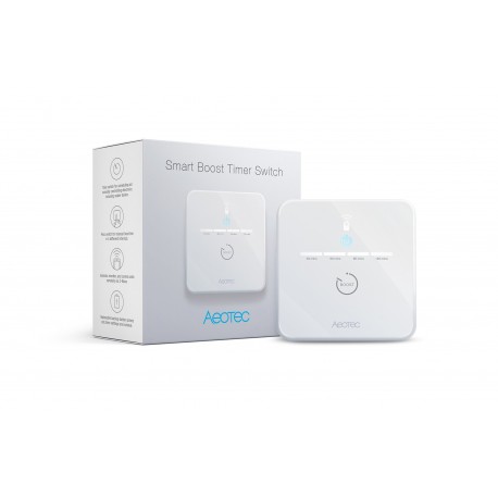
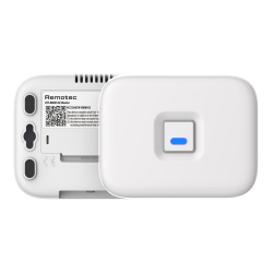
Aeotec Smart Boost Timer Switch - temporizador Z-Wave
AEOEZWA006
Nuevo
Con el interruptor temporizador Smart Boost de Aeotec puede integrar su caldera de agua caliente en la red Z-Wave. Optimice el tiempo en el que necesita el agua caliente de forma individual o mediante los períodos de tiempo preestablecidos de 30, 60, 90 ó 120 minutos.
Sin Stock
- Eliminar de mis favoritos
- Agregar este producto a mis favoritos
- Imprimir
Características técnicas
| Tecnología Domótica | Z-Wave Plus |
Descripción
Con el interruptor temporizador Smart Boost de Aeotec puede integrar su caldera de agua caliente en la red Z-Wave. Optimice el tiempo en el que necesita el agua caliente de forma individual o mediante los períodos de tiempo preestablecidos de 30, 60, 90 ó 120 minutos.
El control se realiza manualmente en el propio Aeotec Smart Boost Timer Switch o en el sistema Z-Wave a través de App. El temporizador puede conmutar cargas de hasta 16A y tiene protección de sobretensión y función de repetidor.
El interruptor temporizador Smart Boost de Aeotec es un dispositivo habilitado para Z-Wave Plus y puede ser incluido/operado en cualquier red Z-Wave con otros dispositivos certificados Z-Wave de otros fabricantes y/o otras aplicaciones. Todos los nodos no operados por baterías dentro de la red actuarán como repetidores, independientemente del proveedor, para aumentar la fiabilidad de la red El conmutador de tiempo Smart Boost de Aeotec soporta la función de medidor de consumo. Cuando el dispositivo ha sido incluido en la red, informará periódicamente de la potencia de consumo. También es un temporizador de cuenta atrás de alta potencia que puede utilizarse para controlar elementos de calentamiento de inmersión u otros aparatos eléctricos con una capacidad de hasta 16A. En el producto, se utilizan cuatro sencillos LED blancos para mostrar al usuario cuánto tiempo queda por correr. Pulsando el interruptor mientras la unidad está en funcionamiento, el usuario puede cancelar el programa de cronometraje, y la función de memoria del temporizador recordará el último período seleccionado.
Características:
Temporizador para el control manual o remoto de los dispositivos conectados
Sólo utilizable en el Reino Unido
Max. Carga: 16A
Fuente de alimentación: 80 - 250V
Protección de sobretensión
Batería de reserva: CR2032 DC 3V
Smart Start y estándar de seguridad S2
Tecnología inalámbrica: Z-Wave Plus
Dimensiones del artículo (AnxAlxAl) 83 x 83 x 47 mm
Dimensiones del paquete (AnxAlxAl) 109 x 109 x 56 mm
Artículo peso neto 0,165 Kg
Artículo peso bruto 0,216 Kg
Z-Wave Plus
Onda Z S2
RAEE
CE
Grado de protección IP20
Información Ampliada Z-Wave (Inglés)
Descargue el manual desde aquí.
2. Put the Z-Wave Primary Controller into inclusion mode (If you don’t know how to do this, refer to its manual)
3. Press and hold the action button, and when the yellow LED is on, release the button. It indicates the device has enter learn mode.
4. If added successfully, the power LED will remain green for 2 seconds, then turn off.
2. Put the Primary Controller into exclusion mode (If you don’t know how to do this refer to its manual)
3. Press and hold the action button, and when the purple LED turns on, release the button. This indicates that the device has entered learn mode. If removal is successful, the blue LED will blink slowly.
1. Make sure the device has been powered.
2. Press and hold the action button for 15 seconds. When the red LED turns on, release the button. Then, the device will enter factory reset mode. If the reset is successful, the LED will blink blue slowly.
1. Power on the device.
a) Press and hold the button about 1 second, when the power LED turns white, release the button. Then the 1st boost time LED will turn on. This indicates that the device entered boost mode. The switch will turn on immediately and will turn off after 30 minutes (This time can be changed through Configuration Parameter 5).
b) Press and hold the button about 1 second after doing a), when the power LED turns white, release the button. The 1st and 2nd boost time LEDs will turn on, which means the switch will turn off after 60 minutes.
c) Press and hold the button about 1 second after doing b), when the power LED turns white release the button. The 1st, 2nd and 3rd boost time LEDs will turn on, which means the switch will turn off after 90 minutes.
d) Press and hold the button about 1 second after doing c), when the power LED turns white release the button. The 1st, 2nd, 3rd, and 4th boost time LEDs will turn on, which means the switch will turn off after 120 minutes.
e) Press and hold the button about 1 second after doing d), when the power LED turn off release the button. Then all of the boost time leds will turn off, which indicates that boost mode has been exited.
2. Press and hold the button about 5 seconds.
a) When the power LED turns green, release the button, and the device will enter an override schedule state. At this state, the schedule task doesn’t work. The switch can only be turned on or off from the gateway.
b) When the power LED turns red, release the button, and the device will exit the override schedule state.


