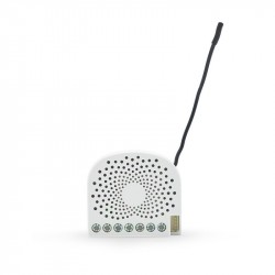
Productos más vistos


Confianza Online


domoticalia.es/es/ Reviews with ekomi.es
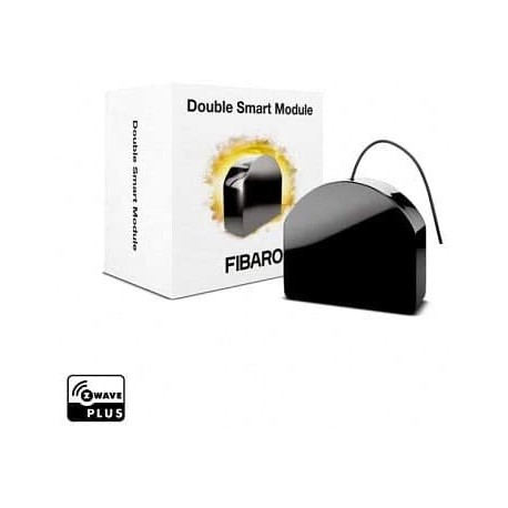
EN OFERTA Fibaro Double Smart Module rele doble Z-wave Ver más grande

Fibaro Double Smart Module - micromódulo ON/OFF doble relé

FGS-224

Nuevo

El módulo inteligente Z-Wave de Fibaro FGS-224 le permitirá controlar dos luces, dispositivos o contactos secos de forma remota mientras mantiene su interruptor existente. 

Más detalles

En Stock - Envío inmediato

63,89 €

-20%

79,86 €

Características técnicas

Tecnología Z-Wave Plus

Descripción

Relé doble para encendido y apagado via radio. Está diseñado para ser instalado en cajas de mecanismo estándar junto a  interruptor de pared, siendo compatible con el interruptor que ya haya y su marco.

También se pueden montar  en cualquier otro lugar donde sea necesario para operar dos dispositivos independientes de 1,5 kW de potencia combinada. El relé Fibaro de doble encendido / apagado  puede encender o apagar los dispositivos conectados ya sea a través de las ondas de radio o mediante los interruptores de pared conectados directamente. 

Módulo inteligente FIBARO Micromódulo de conmutación Z-Wave+
El micromódulo Smart FIBARO ha sido diseñado para activar y desactivar dispositivos eléctricos. Gracias a su pequeño tamaño, puede instalarse en cajas de empalme o en cajas de empotrar. El módulo está controlado por la red de la Onda Z o por un simple interruptor. Conecte su Módulo Inteligente FIBARO a su sistema Z-Wave y a otros dispositivos para disfrutar de posibilidades casi infinitas!

Este módulo tiene dos relés libres de potencial (contacto seco) con una función de temporizador (para crear un impulso), por lo que puede utilizarse tanto para conmutar un voltaje convencional de 230V como cualquier tipo de fuente de alimentación de CC (5V, 12V ... 24V CC). Por lo tanto, se puede utilizar para controlar cualquier tipo de carga como una caldera (conectando el contacto seco en lugar de un termostato) o un operador de puerta de garaje...

Además, tiene una función para evitar la activación simultánea de los 2 relés, esencial en ciertas aplicaciones para evitar los cortocircuitos.

Prácticos bloques de terminales - Fácil instalación
El Módulo Inteligente de FIBARO está equipado con enchufes de sección transversal aumentada que le permiten conectarlo a cables de mayor diámetro y simplificar el proceso de instalación.

Menú de configuración fácil de usar
El diodo RGB integrado es una ayuda valiosa durante el proceso de instalación. La luz mostrará si el Módulo Inteligente de FIBARO ha sido añadido o eliminado de la red. También puede ver si una calibración o actualización ha sido exitosa.

Probador de cobertura de red de onda Z
Use el Módulo Inteligente de FIBARO para comprobar la calidad de la señal en la red de Ondas Z. El LED RGB incorporado le ayudará a comprobar si la ubicación que ha seleccionado para la instalación está dentro de su rango.

Actualizaciones de software
Puede actualizar el software de su Módulo Inteligente FIBARO a la última versión una vez que esté disponible. De esta manera, tienes acceso a las últimas características sin tener que comprar la última versión del dispositivo.

Fácil de instalar
Simplemente coloque el módulo en la caja trasera y conéctelo a una instalación existente. El tamaño en miniatura del módulo permite colocarlo en muchos lugares convenientes.

Gestión de la escena
Incluso las acciones más complejas pueden ser activadas por un interruptor de pared conectado a un módulo. Con una simple pulsación del botón al entrar en una habitación, es tan natural como encender las luces. De 1 a 3 pulsaciones y una pulsación larga se pueden asignar a cuatro acciones diferentes

Su dispositivo móvil es su control remoto
Puede controlar los módulos y recibir información a través de sus ordenadores personales y dispositivos móviles. El Interruptor Único 2 de FIBARO no requiere de costosos paneles de control para funcionar.

Precaución, este módulo requiere neutralidad para funcionar.

FUNCIONES :

Controla dos luces/dispositivos a distancia
Puede instalarse detrás de un interruptor existente (bi-estable o monoestable)
Función ON/OFF
Dos relés libres de potencial (control de la puerta, caldera, puerta de garaje, etc.)
Integra el chip de la serie Z-Wave 500
Una comunicación 250% más rápida comparada con los dispositivos estándar de Onda Z.
Mecanismo integrado de activación de la escena (vía S2)
Clases de comunicación y notificación de seguridad
Menú de configuración con un diodo
Soporta el modo seguro (Z-Wave Network Security) encriptado con codificación AES-128
Probador de cobertura de la red de Onda Z integrada
Actualización del software OTA (dependiente del controlador)
Bloques de terminales más grandes para facilitar el cableado
Forma redondeada para cumplir con los más altos estándares
Pequeño, discreto y estético
Facilidad de uso e instalación

DATOS TÉCNICOS :

Tipo de módulo: Receptor de Onda Z
Alimentación: 100 - 240V~, 50/60Hz o 24 - 30 Vdc
Cableado: 3 cables, se requiere un neutro (a 230V)
Potencia máxima:
Corriente máxima por salida: 6A / 110 - 240V~, 50/60Hz (difiere según el tipo de carga)
Corriente total máxima: 9.5A / 110 - 240V~, 50/60Hz (difiere según el tipo de carga)
Frecuencia: 868.42 Mhz
Distancia de transmisión: 50m de campo libre, 40m en el interior (depende de la estructura del edificio)
Potencia de la señal: 1mW
Dimensiones: 42,5mm x 38,25mm x 20,3mm (L x W x H)
Temperatura de funcionamiento: 0-35°C
Estándares: EC, ROHS, 2011/65/EU, 2014/53/EU, 2015/863, ZWAVE PLUS
Toda la documentación y los manuales del producto Fibaro están disponibles en manuals.fibaro.com.

Información Ampliada Z-Wave (Inglés)

Nombre: FGS-224
Fabricante:FIBARO
Identificador:FGS-224
Número de Certificación Z-Wave:ZC10-20096968
Plataforma Hardware:ZM5101
FLiRS:NO
Tipo de Role:Always On Slave
Descripción Corta:The remotely operated FIBARO Double Smart Module is designed to turn electrical devices or circuits on and off.
Descripción:The remotely operated FIBARO Double Smart Module is designed to turn electrical devices or circuits on and off. Double Smart Module allows to control two devices or circuits. The compact size of the device allows for the product to be installed in the housings of other devices. The devices can be controlled either via the Z-Wave™ network or with buttons connected directly to them.

Descargue el manual desde aquí.

Grupo
Max Nodos
Descripción
1
1
“Lifeline” reports the device status and allows for assigning single device only (main controller by default).
2
5
Is used to turn the associated devices on/off reflecting input operation for 1st channel (uses Basic command class).
3
5
Is used to turn the associated devices on/off reflecting input operation for 2nd channel (uses Basic command class).
Número
Tamaño (Bytes)
Valor por Defecto
Nombre
Descripción
1
1
1
Remember relays state
This parameter determines the state of relays after power supply failure (e.g. power outage). For auto OFF and flashing modes the parameter is not relevant and the relay will always remain switched off.
150
1
0
First channel – operating mode
This parameter allows to choose operating mode for channel controlled with Q/Q1 output. For timed modes (value 1, 2 or 3), time is set with parameter 154 and reaction to input change is set with parameter 152.
152
1
0
First channel - reaction to input change in delayed/auto OFF modes
This parameter determines how the device reacts when changing state of S1 input in timed modes for first channel.
153
1
0
Second channel – reaction to input change in delayed/ auto OFF modes
This parameter determines how the device reacts when changing state of S2 input in timed modes for second channel.
154
2
5
First channel – time parameter for delayed/auto OFF and flashing modes
This parameter allows to set time parameter used in timed modes for first channel. For delayed/ auto OFF modes it determines duration, for flashing mode it determines cycle period.
155
2
5
Second channel – time parameter for delayed/auto OFF and flashing modes
This parameter allows to set time parameter used in timed modes for second channel. For delayed/auto OFF modes it determines duration, for flashing mode it determines cycle period.
156
2
255
ParaS1 input – Switch ON value sent to 2nd association group
This parameter defines value sent with Switch ON command to devices in 2nd association group when using S1 input.
157
2
0
S1 input – Switch OFF value sent to 2nd association group
This parameter defines value sent with Switch OFF command to devices in 2nd association group when using S1 input.
158
2
99
S1 input – Double Click value sent to 2nd association group
This parameter defines value sent with Double Click command to devices in 2nd association group when using S1 input.
159
2
255
S2 input – Switch ON value sent to 3rd association group
This parameter defines value sent with Switch ON command to devices in 3rd association group when using S2 input.
160
2
0
S2 input – Switch OFF value sent to 3rd association group
This parameter defines value sent with Switch OFF command to devices in 3rd association group when using S2 input.
161
2
99
S2 input – Double Click value sent to 3rd association group
This parameter defines value sent with Double Click command to devices in 3rd association group when using S2 input.
162
1
0
Q/Q1 output type
This parameter determines type of Q/Q1 output.
163
1
0
Q2 output type
This parameter determines type of Q2 output.
164
1
0
Lock simultaneous switching of Q1 and Q2 outputs
When the lock is enabled, both outputs cannot be turned on at the same time.
20
1
0
S1 input – switch type
This parameter defines as what type the device should treat the switch connected to the S1 terminal.
21
1
0
Parameter 2
This parameter defines as what type the device should treat the switch connected to the S2 terminal.
24
1
0
Inputs orientation
This parameter allows reversing operation of S1 and S2 inputs without changing the wiring. Use in case of incorrect wiring.
25
1
0
Outputs orientation
This parameter allows reversing operation of Q1 and Q2 outputs without changing the wiring. Use in case of incorrect wiring.
30
4
0
Alarm configuration - 1st slot
This parameter determines to which alarm frames and how the device should react. The parameters consist of 4 bytes, three most significant bytes are set according to the official Z-Wave protocol specification.Default value [0x00, 0x00, 0x00, 0x00] (disabled). The 4 bytes must be converted to a single decimal value to be entered in the gateway sending the configuration parameter value. Example: Event: Home Security (0x07) Status: Motion Detected (0x08) Parameter: None (0x00) Action: turn ON (0x01)=0x07080001 which is 117964801 decimal to be entered in the gateway.
31
4
100597769
Alarm configuration - 2nd slot
This parameter determines to which alarm frames and how the device should react. The parameters consist of 4 bytes, three most significant bytes are set according to the official Z-Wave protocol specification. Default value [0x05, 0xFF, 0x00, 0x00] (Water alarm, any notification, no action). The 4 bytes must be converted to a single decimal value to be entered in the gateway sending the configuration parameter value. Example: Event: Home Security (0x07) Status: Motion Detected (0x08) Parameter: None (0x00) Action: turn ON (0x01)=0x07080001 which is 117964801 decimal to be entered in the gateway.
32
4
33488896
Alarm configuration - 3rd slot
This parameter determines to which alarm frames and how the device should react. The parameters consist of 4 bytes, three most significant bytes are set according to the official Z-Wave protocol specification. Default value [0x01, 0xFF, 0x00, 0x00] (Smoke alarm, any notification, no action). The 4 bytes must be converted to a single decimal value to be entered in the gateway sending the configuration parameter value. Example: Event: Home Security (0x07) Status: Motion Detected (0x08) Parameter: None (0x00) Action: turn ON (0x01)=0x07080001 which is 117964801 decimal to be entered in the gateway.
33
4
50266112
Alarm configuration - 4th slot
This parameter determines to which alarm frames and how the device should react. The parameters consist of 4 bytes, three most significant bytes are set according to the official Z-Wave protocol specification. Default value [0x02, 0xFF, 0x00, 0x00] (CO alarm, any notification, no action). The 4 bytes must be converted to a single decimal value to be entered in the gateway sending the configuration parameter value. Example: Event: Home Security (0x07) Status: Motion Detected (0x08) Parameter: None (0x00) Action: turn ON (0x01)=0x07080001 which is 117964801 decimal to be entered in the gateway.
34
4
83820544
Alarm configuration - 5th slot
This parameter determines to which alarm frames and how the device should react. The parameters consist of 4 bytes, three most significant bytes are set according to the official Z-Wave protocol specification. Default value [0x041, 0xFF, 0x00, 0x00] (Heat alarm, any notification, no action). The 4 bytes must be converted to a single decimal value to be entered in the gateway sending the configuration parameter value. Example: Event: Home Security (0x07) Status: Motion Detected (0x08) Parameter: None (0x00) Action: turn ON (0x01)=0x07080001 which is 117964801 decimal to be entered in the gateway.
35
2
600
Alarm configuration – duration
This parameter defines duration of alarm sequence. When time set in this parameter elapses, alarm is cancelled and relays restore normal operation, but do not recover state from before the alarm.
40
1
15
S1 input – scenes sent
This parameter determines which actions result in sending scene IDs assigned to them. Values can be combined (e.g. 1+2=3 means that scenes for single and double click are sent). Enabling scenes for triple click disables entering the device in learning mode by triple clicking.
41
1
15
S2 input – scenes sent
This parameter determines which actions result in sending scene IDs assigned to them. Values can be combined (e.g. 1+2=3 means that scenes for single and double click are sent). Enabling scenes for triple click disables entering the device in learning mode by triple clicking.
Basic
COMMAND_CLASS_BASIC
Application Status
COMMAND_CLASS_APPLICATION_STATUS
Association Group Information V2
COMMAND_CLASS_ASSOCIATION_GRP_INFO_V2
Association V2
COMMAND_CLASS_ASSOCIATION_V2
Basic
COMMAND_CLASS_BASIC
Central Scene V3
COMMAND_CLASS_CENTRAL_SCENE_V3
Configuration
COMMAND_CLASS_CONFIGURATION
CRC16 Encapsulation
COMMAND_CLASS_CRC_16_ENCAP
Device Reset Locally
COMMAND_CLASS_DEVICE_RESET_LOCALLY
Firmware Update Meta-Data V4
COMMAND_CLASS_FIRMWARE_UPDATE_MD_V4
Manufacturer Specific V2
COMMAND_CLASS_MANUFACTURER_SPECIFIC_V2
Multi-Channel Association V3
COMMAND_CLASS_MULTI_CHANNEL_ASSOCIATION_V3
Multi-Channel V4
COMMAND_CLASS_MULTI_CHANNEL_V4
Notification V8
COMMAND_CLASS_NOTIFICATION_V8
Powerlevel
COMMAND_CLASS_POWERLEVEL
Protection V2
COMMAND_CLASS_PROTECTION_V2
Security S0
COMMAND_CLASS_SECURITY
Security S2
COMMAND_CLASS_SECURITY_2
Supervision
COMMAND_CLASS_SUPERVISION
Switch Binary
COMMAND_CLASS_SWITCH_BINARY
Transport Service V2
COMMAND_CLASS_TRANSPORT_SERVICE_V2
Version V2
COMMAND_CLASS_VERSION_V2
Z-Wave Plus Info V2
COMMAND_CLASS_ZWAVEPLUS_INFO_V2
Classic Inclusion
To add the device to the Z-Wave network manually:

1. Power the device.

2. Set the main controller in (Security/non-Security Mode) add mode

(see the controller’s manual).

3. Quickly, three times click button connected to S1/S2 or the

maintenance button.

4. LED will start blinking yellow, wait for the adding process to end.

5. If you are adding in Security S2 Authenticated, input the underlined

part of the DSK (label on the bottom of the box).

6. Adding result will be confirmed by the Z-Wave controller’s message

and the LED:

• Green – successful (non-secure, S0, S2 non-authenticated),

• Magenta – successful (Security S2 Authenticated),

• Red – not successful.
Classic Exclusion
To remove the device from the Z-Wave network:

1. Power the device.

2. Set the main controller into remove mode (see the controller’s

manual).

3. Quickly, three times click the maintenance button.

4. LED will start blinking yellow, wait for the removing process to

end.

5. Successful removing will be confirmed by the Z-Wave controller’s

message and red LED colour.
Factory Reset Procedure
1. Press and hold the maintenance button to enter the menu.

2. Release button when the device glows yellow.

3. Quickly click the button to confirm.

4. After few seconds the device will be restarted, which is signalled

with red LED colour.
Where to find S2 DSK on product
If you are adding in Security S2 Authenticated, input the underlined

part of the DSK (label on the bottom of the box).
S2 Authenticated
S2_AUTHENTICATED
S2 Unauthenticated
S2_UNAUTHENTICATED
Electric Load Type
Select the electric load type(s) supported by the device.
Firmware Updatable
Indicates whether the firmware can be updated and whether it is done by the consumer or a technician.
Z-Wave Scene Type
Indicates which of the two types of Z-Wave scene command classes are supported. Scenes or Central Scene
Color
If the product is only available in one color, pick the color from the list.


Opiniones

grado 
01/03/2021

Rele doble de contacto seco

Muy util. Me llego pronto. Antes de lo previsto.

¡Escriba su opinión!

Escribe tu opinión

Fibaro Double Smart Module  - micromódulo ON/OFF doble relé

Fibaro Double Smart Module - micromódulo ON/OFF doble relé

El módulo inteligente Z-Wave de Fibaro FGS-224 le permitirá controlar dos luces, dispositivos o contactos secos de forma remota mientras mantiene su interruptor existente. 
30 otros productos de la misma categoría:

Los clientes que compraron este producto también han comprado...