Produtos visualizados


Confianza Online


domoticalia.es/es/ Reviews with ekomi.es

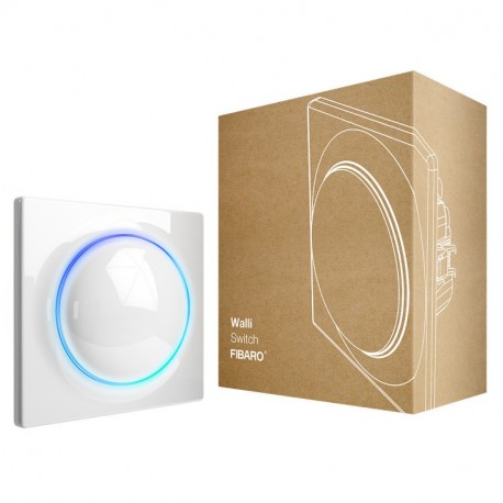
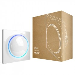
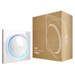
FIBARO - Interruptor Walli

FGWDSEU-221

Novo

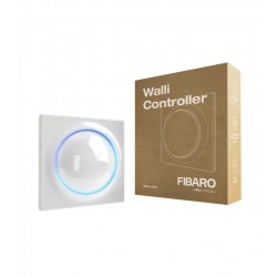
O switch FIBARO Walli é um switch inteligente que pode controlar uma ou duas cargas de forma independente. Compatível com Z-Wave

Mais detalhes

Em estoque

108,61 €

-12%

123,42 €

Características tecnicas

Tecnologia Domótica Z-Wave Plus

Mais Informação

Interruptor inteligente Z-Wave + interruptor Fibaro Walli

O FIBARO Walli Switch é um interruptor inteligente que pode controlar uma ou duas cargas de forma independente. Ele é projetado para instalação rápida em caixas embutidas e é equipado com um anel de LED e os recursos conhecidos e reconhecidos dos módulos Fibaro.

Design exclusivo e tecnologia excepcional

A série completa de conectores e conectores inteligentes FIBARO baseados na tecnologia Z-Wave proporcionará à sua casa uma inteligência versátil. O visual da série é inspirado em uma pérola - sua sofisticação intemporal e bela forma que completa qualquer interior.

Fibaro Walli

Anel LED para combinar com sua casa

Escolha sua cor favorita

Selecione a cor do anel de LED para adaptá-lo às suas preferências pessoais.

Botão duplo de luz de fundo

Use duas cores de luz de fundo onde quiser - uma cor diferente na parte inferior e outra na parte superior para ver o status exato do dispositivo.

Uma visão geral do consumo de energia

Controle a quantidade de energia consumida pelo equipamento em sua casa.

Componentes confiáveis e detalhes atraentes

Na FIBARO, qualidade e design únicos sempre andam de mãos dadas. A linha Walli foi projetada para melhorar o conforto e a segurança de sua família por muitos anos.

Fibaro Walli

Pulsações a gosto

Configure o botão de comutador Walli para aproveitar ao máximo seus incríveis recursos.

Um único clique para acender a luz, um duplo clique para desligá-lo, um clique triplo para ativar a cena "Fun", uma pulsação mantida para intensidade de luz de 60%.

Compatível com produtos de outros fabricantes

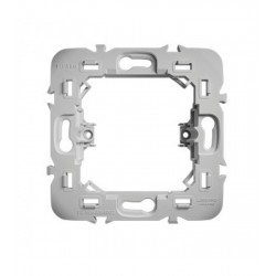
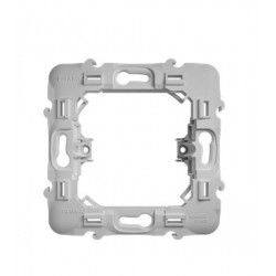
O FIBARO Walli é compatível (com adaptadores) com placas frontais de outros fabricantes: GIRA - System 55, Legrand - Céliane, Schneider - Odace. Se estiver conectado a tomadas e comutadores existentes, equipe-os com uma peça inteligente integrada e aproveite os recursos de uma casa inteligente sem precisar substituir o painel frontal.

Fibaro Walli

Gerencie toda a casa com voz

Os interruptores e tomadas inteligentes da Walli são totalmente compatíveis com os famosos assistentes de voz do Google Assistant e do Amazon Alexa. Gerenciamento de voz fácil e confortável de toda a casa.

Seja com sua casa onde quer que você esteja

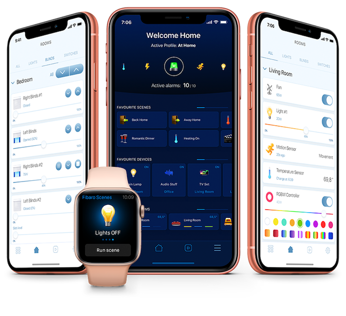
A aplicação móvel FIBARO Home Center permite-lhe gerir interruptores e tomadas inteligentes com o seu smartphone, tablet ou smartwatch. Mantenha tudo sob controle como um chefe.
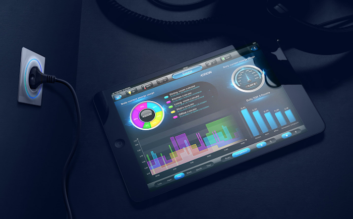
Consumo de energia controlada

Dê uma olhada em sua casa, analise o consumo de energia de seus aparelhos e otimize suas despesas como sempre quis.
Dê um passo adiante no futuro

A série Walli da FIBARO inclui interruptores e tomadas clássicas e não inteligentes para manter constante a estética da sua casa. Escolha-os como desejar e desfrute de um design e recursos exclusivos.

Atenção: tenha cuidado, este interruptor requer que o neutro opere.

FUNÇÕES

Gerencie dispositivos e cenas com um único clique.
Gerenciamento remoto de dispositivos elétricos.
Gestão de dispositivos através de comandos de voz.
Adaptação do anel luminoso às preferências do usuário.
Notificações de falhas de equipamentos elétricos.
Controle do consumo de energia.

AS ESPECIFICAÇÕES TÉCNICAS

Potência: 110-230V 50 / 60Hz
Corrente de carga nominal: 13 A por canal, 16 Um total
Tipos de carga suportados: lâmpadas tubulares incandescentes, transformadores eletrônicos, transformadores ferromagnéticos, LEDs.
Radiofreqüência: 868.0-868.6 megahertz
Âmbito: até 40 m no interior (dependendo do terreno e da estrutura do edifício)
Potência máxima de transmissão: + 6dBm
Temperatura de operação: 0-35 ° C
Umidade ambiente: 10-95% RH sem condensação
Para instalação em caixas: Ø = 60mm, profundidade e 40mm
Dimensões (A x L x P): 86 x 86 x 51 mm

Toda a documentação e instruções dos produtos Fibaro estão disponíveis no site manuals.fibaro.com

Informação alargada da Z-Wave (Inglês)

Nome: Wall Switch
Fabricante:FIBARO
Identificador:FGWDSEU-221
Número de Certificação Z-Wave :ZC10-19106772
Plataforma de Hardware :ZM5101
FLiRS:Não
Tipo de Role :Always On Slave
Descrição breve :FIBARO Walli Single Switch is a smart wall switch designed to control one or two light sources via Z-Wave network.
Descrição :FIBARO Walli Single Switch is a smart wall switch designed to control one or two light sources via Z-Wave network. It measures active power and energy consumed by the controlled load. You can install it with provided cover plate or other compatible. Main features of FIBARO Walli Double Switch: - Can be used with: o Conventional incandescent and halogen light sources, o LED lamps, o Fluorescent lamps, o Electronic transformers (for ELV halogen lamps and LED bulbs), o Ferromagnetic transformers (for MLV halogen lamps). - Can be used with provided cover plate or one of the following: o GIRA – System 55 (Standard 55, E2, Event, Event Clear), o Legrand – Céliane, o Schneider – Odace. - Active power and energy consumption metering. - Supports Z-Wave network Security Modes: S0 with AES-128 encryption and S2 Authenticated with PRNG-based encryption. - Works as Z-Wave signal repeater (all non-battery operated devices within the network will act as repeaters to increase reliability of the network). - May be used with all devices certified with the Z-Wave Plus certificate and should be compatible with such devices produced by other manufacturers.

Descarregue o manual a partir de aqui.

Grupo
Nodos máximos
Descrição
1
1
“Lifeline” reports the device status and allows for assigning single device only (main controller by default).
2
5
“On/Off” is used to turn the associated devices on/off reflecting button operation (uses Basic command class).
3
5
“Dimmer” is used to change level of associated devices reflecting button operation (uses Switch Multilevel command class).
Número
Tamanho (Bytes)
Valor por defeito
Nome
Descrição
1
1
1
Remember device state
This parameter determines how the device will react in the event of power supply failure (e.g. power outage). The parameter is not relevant for outputs set to pulse mode (parameter 150/151 set to 2).
10
4
36800
LED frame – power limit
This parameter determines maximum active power. Exceeding it results in the LED frame flashing violet. Function is active only when parameter 11 is set to 8 or 9.
11
1
1
LED frame – colour when ON
This parameter defines the LED colour when thedevice is ON. When set to 8 or 9, LED frame colour will change depending on he measured power and parameter 10. Other colours are set permanently and do not depend on power consumption.
12
1
0
LED frame – colour when OFF
This parameter defines the LED colour when the device is OFF.
13
1
100
LED frame – brightness
This parameter allows to adjust the LED frame brightness.
150
1
0
First channel – operating mode
This parameter allows to choose operating for the 1st channel .
151
1
0
Second channel – operating mode
This parameter allows to choose operating for the 2nd channel.
152
1
0
First channel - reaction to switch for delayed OFF / pulse modes
This parameter determines how the device in timed mode reacts to pushing the button for 1st channel. The parameter is relevant only for button toggles modes (parameter 20 set to 1 or 3).
153
1
0
Second channel - reaction to switch for delayed OFF / pulse modes
This parameter determines how the device in timed mode reacts to pushing the button for 2nd channel. The parameter is relevant only for button toggles modes (parameter 20 set to 1 or 3).
154
2
50
First channel - time parameter for delayed OFF / pulse modes
This parameter allows to set time parameter used in timed modes for 1st channel (parameter 150). Delay time for switching off or duration of the pulse.
155
2
50
Second channel - time parameter for delayed OFF / pulse modes
This parameter allows to set time parameter used in timed modes for 2nd channel (parameter 151). Delay time for switching off or duration of the pulse.
156
2
255
First channel – Switch ON value sent to 2nd and 3rd association groups
This parameter defines value sent with Switch ON command to devices associated in 2nd and 3rd association group for manual changes of Endpoint 1 state.
157
2
0
First channel – Switch OFF value sent to 2nd and 3rd association groups
This parameter defines value sent with Switch OFF command to devices associated in 2nd and 3rd association group for manual changes of Endpoint 1 state.
158
2
99
First channel – Double Click value sent to 2nd and 3rd association groups
This parameter defines value sent with Double Click command to devices associated in 2nd and 3rd association group for manual changes of Endpoint 1 state.
159
2
255
Second channel – Switch ON value sent to 4th and 5th association groups
This parameter defines value sent with Switch ON command to devices associated in 4th and 5th association group for manual changes of Endpoint 2 state.
160
2
0
Second channel – Switch OFF value sent to 4th and 5th association groups
This parameter defines value sent with Switch OFF command to devices associated in 4th and 5th association group for manual changes of Endpoint 2 state.
161
2
99
Second channel – Double Click value sent to 4th and 5th association groups
This parameter defines value sent with Double Click command to devices associated in 4th and 5th association group for manual changes of Endpoint 2 state.
2
4
0
First channel – overload safety switch
This function allows to turn off the controlled device in case of exceeding the defined power. Controlled device can be turned back on via button or sending a control frame.
20
1
1
Buttons operation
This parameter defines how device buttons should control the channels.
24
1
0
Buttons orientation
This parameter allows reversing the operation of the buttons.
25
1
0
Outputs orientation
This parameter allows reversing the operation of Q1 and Q2 without changing the wiring (e.g. in case of invalid connection). Changing orientation turns both outputs off.
3
4
0
Second channel – overload safety switch
This function allows to turn off the controlled device in case of exceeding the defined power. Controlled device can be turned back on via button or sending a control frame.
30
4
0
Alarm configuration - 1st slot
This parameter determines to which alarm frames and how the device should react. The parameters consist of 4 bytes, three most significant bytes are set according to the official Z-Wave protocol specification.
31
4
0
Alarm configuration - 2nd slot
This parameter determines to which alarm frames and how the device should react. The parameters consist of 4 bytes, three most significant bytes are set according to the official Z-Wave protocol specification.
32
4
0
Alarm configuration - 3rd slot
This parameter determines to which alarm frames and how the device should react. The parameters consist of 4 bytes, three most significant bytes are set according to the official Z-Wave protocol specification.
33
4
0
Alarm configuration - 4th slot
This parameter determines to which alarm frames and how the device should react. The parameters consist of 4 bytes, three most significant bytes are set according to the official Z-Wave protocol specification.
34
4
0
Alarm configuration - 5th slot
This parameter determines to which alarm frames and how the device should react. The parameters consist of 4 bytes, three most significant bytes are set according to the official Z-Wave protocol specification.
35
2
600
Alarm configuration – duration
This parameter defines duration of alarm sequence. When time set in this parameter elapses, alarm is cancelled, LED frame and relay restore normal operation, but do not recover state from before the alarm.
40
1
0
First button – scenes sent
This parameter determines which actions result in sending scene IDs assigned to them. Values can be combined (e.g. 1+2=3 means that scenes for single and double click are sent). Enabling scenes for triple click disables entering the device in learn mode by triple clicking.
41
1
0
Second button – scenes sent
This parameter determines which actions result in sending scene IDs assigned to them. Values can be combined (e.g. 1+2=3 means that scenes for single and double click are sent). Enabling scenes for triple click disables entering the device in learn mode by triple clicking.
60
1
0
Power reports – include self-consumption
This parameter determines whether the power measurements should include power consumed by the device itself.
61
2
15
Power reports for first channel – on change
This parameter defines minimal change (from the last reported) in measured power that results in sending new report. For loads under 50W the parameter is irrelevant, report are sent every 5W change.
62
2
3600
Power reports for first channel – periodic
This parameter defines reporting interval for measured power. Periodic reports are independent from changes in value (parameter 61).
63
2
15
Power reports for second channel – on change
This parameter defines minimal change (from the last reported) in measured power that results in sending new report. For loads under 50W the parameter is irrelevant, report are sent every 5W change.
64
2
3600
Power reports for second channel – periodic
This parameter defines reporting interval for measured power. Periodic reports are independent from changes in value (parameter 63).
65
2
10
Energy reports for first channel – on change
This parameter defines minimal change (from the last reported) in measured energy that results in sending new report.
66
2
3600
Energy reports for first channel – periodic
This parameter defines reporting interval for measured energy. Periodic reports are independent from changes in value (parameter 66).
67
2
10
Energy reports for second channel – on change
This parameter defines minimal change (from the last reported) in measured energy that results in sending new report.
68
2
3600
Energy reports for second channel – periodic
This parameter defines reporting interval for measured energy. Periodic reports are independent from changes in value (parameter 67).
Basic
COMMAND_CLASS_BASIC
Application Status
COMMAND_CLASS_APPLICATION_STATUS
Association Group Information V2
COMMAND_CLASS_ASSOCIATION_GRP_INFO_V2
Association V2
COMMAND_CLASS_ASSOCIATION_V2
Basic
COMMAND_CLASS_BASIC
Central Scene V3
COMMAND_CLASS_CENTRAL_SCENE_V3
Configuration
COMMAND_CLASS_CONFIGURATION
CRC16 Encapsulation
COMMAND_CLASS_CRC_16_ENCAP
Device Reset Locally
COMMAND_CLASS_DEVICE_RESET_LOCALLY
Firmware Update Meta-Data V4
COMMAND_CLASS_FIRMWARE_UPDATE_MD_V4
Manufacturer Specific V2
COMMAND_CLASS_MANUFACTURER_SPECIFIC_V2
Meter V3
COMMAND_CLASS_METER_V3
Multi-Channel Association V3
COMMAND_CLASS_MULTI_CHANNEL_ASSOCIATION_V3
Multi-Channel V4
COMMAND_CLASS_MULTI_CHANNEL_V4
Notification V8
COMMAND_CLASS_NOTIFICATION_V8
Powerlevel
COMMAND_CLASS_POWERLEVEL
Protection V2
COMMAND_CLASS_PROTECTION_V2
Security S0
COMMAND_CLASS_SECURITY
Security S2
COMMAND_CLASS_SECURITY_2
Supervision
COMMAND_CLASS_SUPERVISION
Switch Binary
COMMAND_CLASS_SWITCH_BINARY
Transport Service V2
COMMAND_CLASS_TRANSPORT_SERVICE_V2
Version V2
COMMAND_CLASS_VERSION_V2
Z-Wave Plus Info V2
COMMAND_CLASS_ZWAVEPLUS_INFO_V2
Device Wake-Up
FIBARO Walli Double Switch is powered using DC power supply unit so it is always awake.
Classic Exclusion
To remove the device from the Z-Wave network:

1. Power the device.

2. Set the main controller into remove mode (see the controller’s manual).

3. Quickly, three times click one of the buttons.

4. LED will start blinking yellow, wait for the removing process to end.

5. Successful removing will be confirmed by the Z-Wave controller’s message and red LED colour.

Factory Reset Procedure
Reset procedure allows to restore the device back to its factory settings, which means all information about the Z-Wave controller and user configuration will be deleted. Resetting to factory defaults does not reset energy consumption memory.

1. Quickly, three times click, then press and hold one of the buttons to enter the menu.

2. Release the button when the device glows yellow.

3. Quickly click the button to confirm.

4. After a few seconds the device will be restarted, which is signalled with the red LED colour.

Where to find S2 DSK on product
Page 12, chapter 5.1:


"If you are adding in Security S2 Authenticated, input the underlined part of the DSK (label on the bottom of the box)."
Classic Inclusion
To add the device to the Z-Wave network manually:

1. Power the device.

2. Set the main controller in (Security/non-Security Mode) add mode (see the controller’s manual).

3. Quickly, three times click one of the buttons.

4. If you are adding in Security S2 Authenticated, scan the DSK QR code or input the underlined part of the DSK (label on the bottom of the box).

5. LED will start blinking yellow, wait for the adding process to end.

6. Adding result will be confirmed by the Z-Wave controller’s message and the LED frame:

- Green - successful (non-secure, S0, S2 non-authenticated),

- Magenta - successful (Security S2 Authenticated),

- Red – not successful.


To add the device to the Z-Wave network using SmartStart:

1. Set the main controller in Security S2 Authenticated add mode (see the controller’s manual).

2. Scan the DSK QR code or input the underlined part of the DSK (label on the bottom of the box).

3. Power the device.

4. Wait for the adding process to start (up to few minutes), which is signaled with yellow LED blinking.

5. Adding result will be confirmed by the Z-Wave controller’s message and the LED frame:

- Green - successful (non-secure, S0, S2 non-authenticated),

- Magenta - successful (Security S2 Authenticated),

- Red – not successful.

S2 Authenticated
S2_AUTHENTICATED
S2 Unauthenticated
S2_UNAUTHENTICATED
Switch Load Capacity Current
The amount of switch load energy the product is rated for in Amps
Switch Type
Describes the type of operator for a switch.
Electric Load Type
Select the electric load type(s) supported by the device.
Color
If the product is only available in one color, pick the color from the list.
Loads Controlled
The number of different loads controllable by the product if it supports more than one.
Supported Meter Type
Indicate which type of metering is supported by the device.
Supported Notification Types
Select the Notification Types that the product handles (controllers), or sends (slaves).


Avaliações

Escrever uma avaliação

FIBARO - Interruptor Walli

FIBARO - Interruptor Walli

O switch FIBARO Walli é um switch inteligente que pode controlar uma ou duas cargas de forma independente. Compatível com Z-Wave

14 outros produtos na mesma categoria:

Clientes que compraram este produto também compraram: